
Cable construction
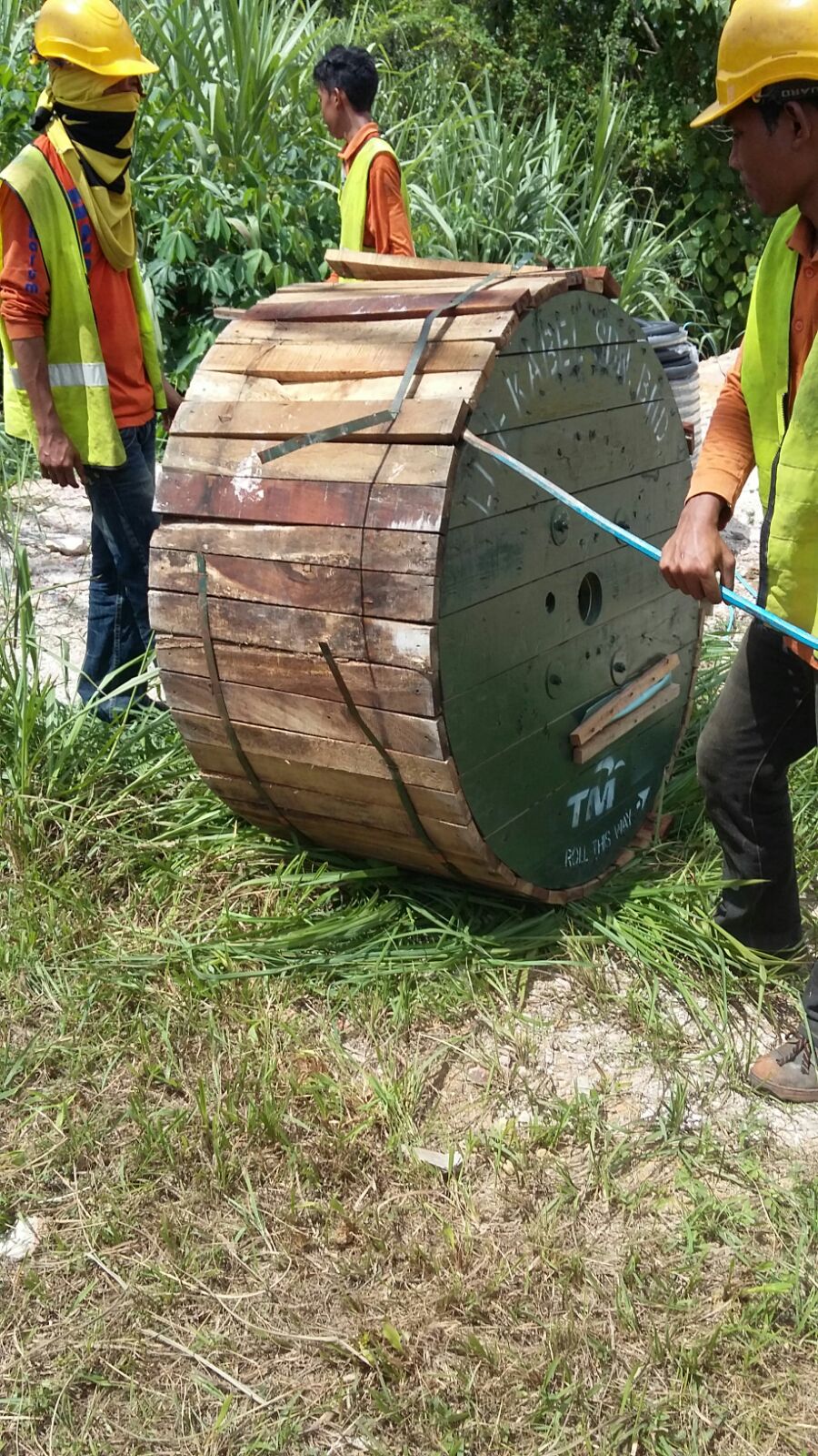
1. Pulling
Existing cables inside manholes are identified and confirmed to avoid confusion during jointing works. Rodding allotted duct to confirm condition of duct before use followed by installing draw rope for pulling of cable. Competent workers are important during pulling works in order to protect the cables and efficiency of works especially for fiber optic cables which require unique approach for handling as compared to copper/jelly filled cable.
Cables are pulled along the new alignment until the designated cut-off location. The location of the jointing between new and existing cables depends on the type of cables, and suitability of the location. For copper cables, the jointing can be done on the nearest possible manhole (subject to authority approval) and for fibre optic cables the minimum acceptable distance between joint is 2 km (joint to joint).
For fibre optic cable, it need to be pulled inside sub-ducts which protect the cables from injury by any outside material. Each duct can only accommodate three sub-ducts and each sub-ducts can only carry one cable only. Once the cable is pulled, all the necessary accessories shall be installed accordingly.
All cables must be securely placed at every manhole and joint box. Cable ties shall be used to ties the cables to the brackets. Arrangement of cable shall be visually neat and tidy. The cable shall not be crossed between each other.
A spare length, coils of cable, minimum of 5 meters must be left at every intermediate manhole or joint boxes. This cables shall be coiled in a proper manner i.e. to be tied at four locations and securely placed on cable bracket bearers. If a cable bracket bearer is not present, the contractor shall ensure that the cables are neatly organized.
The coils must be vertically placed on one side of the wall neither crossing the existing cables nor blocking any duct entrance and placed nearest to the duct configuration. At least two bracket bearers, placed at the top and bottom side, must be used.
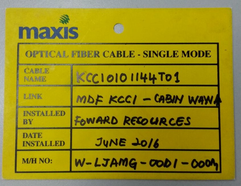
The contractor must provide cable identification tags for each cable in every manhole and joint box. This is to avoid any confusion also acts as a reference during future jointing activities. The tags shall be of a plastic type and technically agreed by service providers/operator.
The tags shall contains information as follows:
a) Cable name
b) Link name
c) Installed by
d) Date of installation
e) Main hole number
In cases where cables are pulled through without any splicing being done at the manholes or joint boxes, cable identification tags shall be provided at each cable branch.
All the cable ends must be capped with an approved heat shrinkable end cap or any other approved type to prevent water penetration. At termination point, a cable length of approximately 5 meters shall be spared inside the manhole or joint box before splicing being carried out. The purpose is to accommodate future maintenance works.
The contractor shall close properly all manhole covers before leaving the site. The contractor must ensure the site is tidy and clean during and after cable installation. Good housekeeping is essential during execution of the works.
Jointing work shall be conducted by competent workers only. The jointing equipments and test gears shall be in good working conditions duly calibrated and certified by approved and relevant authorities.
Jointing work between the new and existing cables shall be done after getting approval from respective authority. The number of cut-over work (jointing work) for a day shall be subjected to authority approval and witnessed by respective authority. All cables shall be activated immediately after the work completion to minimize customer disruptions.
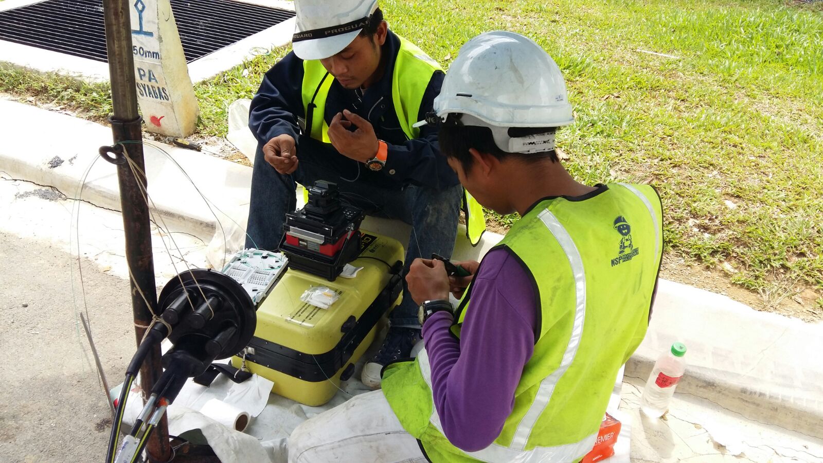
2. Splicing
Splicing and Termination Hardware
Splicing and termination hardware’s are the final category of components to be chosen. Most OSP single mode fiber is fusion spliced for low loss, low reflectance and reliability. Multi mode fiber, especially OM2, 3 and 4, is also easily fusion spliced, but if only a few splices are necessary, mechanical splicing may provide adequate performance and reliability.
Finished splices are placed in a splice tray and placed in a splice closure outdoors or optionally in trays on patch panels indoors. They are sealed to prevent moisture and are designed to be unsealed for repair or re-routing fibers. Splice closures are available in hundreds of designs, depending on the placement of the closure, for example underground in a manhole or vault, above ground in a pedestal, buried underground or mounted on a pole. Closures must also be chosen by the number and types of cables being spliced and whether they enter at both ends and only one. The numbers of cables and splices that a closure can accommodate will determine the size of the closure, and those for high fiber count cables can get quite large.
Splice trays generally hold twelve single fiber fusion splices but may hold fewer ribbon or mechanical splices. Each splice tray shall securely hold the splice and have a cover to protect the fibers when stacked in the closure.
Single mode fibers are best terminated by fusion splicing factory-made pigtails onto fibers in the cable and protecting the splices in a closure or patch panel tray. If termination is done directly on multimode OSP cables, breakout kits will be necessary to sleeve fibers for reliability when connectors are directly attached. This takes more installation time than splicing pre-terminated pigtails on the cables, as is common with single mode fiber cables, and may not save any costs. Even complete preterminated outside cable plant systems are becoming available, reducing the time necessary for termination and splicing.
Outdoor terminations are sometimes housed in pedestals or equipment housings such as those used for local phone switches or traffic control systems. Some of these closures may not be fully sealed from dust and moisture, in which case it is recommended that the fiber connections be inside a more protective housing to prevent future unreliability.
Choosing the proper components for OSP installations is time consuming and unavoidable to ensure reliable and efficient system operation. Once components are chosen, the materials lists are added to the documentation for purchase, installation and future reference.
Planning for the Installation
The completion and documentation of the design of a fiber optic project marks the beginning of the actual task. The next step is to plan for the actual installation. Planning for the installation is a critical phase of any project as it involves coordinating activities of many people and companies. The best way to keep everything straight is probably to develop a check list based on the design during the early stages of the project.
3. Testing & Commissioning
Developing a Test Plan
Every installation requires confirmation that components are installed properly. The installer or contractor needs to ensure the work is being conducted in the best possible practices meeting the customer satisfaction and possibly avoid unnecessary repair. Customers generally require test results as well as a final visual inspection as part of the documentation of a proper installation before approval of payments for works done.
In our experience, however, there is often confusion about exactly what should be tested and how documentation of test results is to be done on fiber optic projects. These issues should be agreed upon during the design phase of the project. Project paperwork should include specifications for testing, references to industry standards and acceptable test results based on a propagation loss budget analysis done during the design phase of the project.
Required vs. Optional Testing
Testing a complete cable plant requires insertion loss testing with a source and power meter or optical loss test set (OLTS) in accordance with the standard test procedure. The test plan should specify the “0 dB” reference method option (one, two or three reference cables) as this will affect the value of the loss. Some standards call for a one cable reference, but this may not be possible with all combinations of test sets and cable plant connectors. The required test methods need to be agreed upon by the contractor and user beforehand. FOA standards provide a simple solution to this problem.
OTDR testing is generally done on outside plant cables, but OTDR testing alone is often not acceptable for cable plant certification. Long lengths of outside plant cabling which include splices should be tested with an OTDR to verify splice performance and look for problems caused by stress on the cable during installation.
While there are advocates of using OTDRs to test any cable plant installation, including short premises cables, it is generally not required by industry standards nor is it appropriate for short links common to premises cabling. The shorter lengths of premises cabling runs and frequent connections with high reflectance often create confusing OTDR traces that cause problems for the OTDR auto test function and are sometimes difficult for even experienced OTDR users to interpret properly.
Long OSP cables may require special testing for spectral attenuation, chromatic dispersion and polarization mode dispersion. These are specialized tests required to ensure DWDM and high bit rate systems operate properly.
Testing and Troubleshooting
You must have available proper test equipment to troubleshoot and restore a cable plant. An OLTS should also have a power meter to test the power of the signals to determine if the problem is in the electronics or cable plant. Total failure of all fibers in the cable plant means a break or cut in the cable. For premises cables, finding the location is often simple if you have a visual fault locator or VFL, which is a bright red laser coupled into the optical fiber that allows testing continuity, tracing fibers or finding bad connectors at patch panels.
For longer cables, an OTDR will be useful. Outside plant networks should use the OTDR to document the cable plant during installation, so during restoration a simple comparison of installation data with current traces will usually find problems. OTDRs can also find non-catastrophic problems, for example when a cable is kinked or stressed, so it only has higher loss, which can also cause network problems.
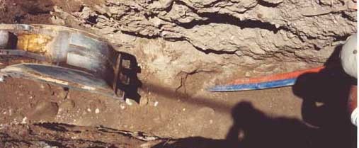
Planning for Restoration
About once a day in the Malaysia, a fiber optic cable is broken by a contractor digging around the cable, as this photo shows. Premises cables are not as vulnerable, except for damage caused by clumsy personnel or during the removal of abandoned cables. Any network is susceptible to damage so every installation needs a restoration plan.
Efficient fiber optic restoration depends on how fast the problem been identified, knowing how to fix it, having the right parts and getting the job done quickly and efficiently. Like any type of emergency, planning ahead will minimize the problems encountered.